As a supplier of OPGW Strain Clamps, ensuring the proper grounding of these clamps is of utmost importance. Grounding is not only crucial for the safety of the electrical grid but also for the efficient operation of the optical fiber communication system integrated within the OPGW (Optical Power Ground Wire). In this blog, I will share some key strategies and considerations on how to ensure the grounding of OPGW Strain Clamps.
Understanding the Importance of Grounding OPGW Strain Clamps
OPGW cables are used in power transmission lines to provide both electrical grounding and optical communication capabilities. The strain clamps are responsible for holding the OPGW cable in place at the suspension points and towers. Proper grounding of these clamps helps to:
- Safety: Protect personnel and equipment from electrical hazards by providing a low - resistance path for fault currents to flow into the ground.
- Lightning Protection: Divert lightning strikes safely to the ground, preventing damage to the OPGW cable and associated equipment.
- Electrical Stability: Maintain the electrical integrity of the power system by minimizing the effects of electrical surges and transient overvoltages.
Selecting the Right Grounding Materials
The first step in ensuring proper grounding of OPGW Strain Clamps is to select the appropriate grounding materials. High - quality grounding conductors, such as copper or aluminum, should be used. These materials have low resistivity, which allows for efficient current flow during fault conditions.
- Copper Grounding Conductors: Copper is a popular choice due to its excellent electrical conductivity, corrosion resistance, and mechanical strength. It can withstand high fault currents without significant degradation.
- Aluminum Grounding Conductors: Aluminum is a lightweight and cost - effective alternative to copper. However, it requires special connectors and installation techniques to prevent corrosion and ensure good electrical contact.
Proper Installation of Grounding Conductors
Once the grounding materials are selected, proper installation is crucial. The grounding conductors should be connected to the OPGW Strain Clamps in a way that ensures low - resistance electrical contact.
- Cleaning the Contact Surfaces: Before making the connection, the contact surfaces of the strain clamp and the grounding conductor should be cleaned to remove any dirt, oxide, or other contaminants. This can be done using a wire brush or a suitable cleaning agent.
- Using Appropriate Connectors: High - quality connectors, such as compression connectors or bolted connectors, should be used to join the grounding conductor to the strain clamp. These connectors should be tightened to the manufacturer's specifications to ensure a secure and low - resistance connection.
- Routing the Grounding Conductors: The grounding conductors should be routed in a straight and direct path to the ground electrode. Avoid sharp bends or kinks in the conductors, as these can increase the resistance and reduce the effectiveness of the grounding system.
Grounding Electrodes
A reliable grounding electrode is essential for the proper functioning of the grounding system. The grounding electrode provides a connection between the grounding conductor and the earth.
- Rod Electrodes: Copper - clad steel or solid copper rods are commonly used as grounding electrodes. These rods are driven into the ground to a sufficient depth to ensure good electrical contact with the soil.
- Plate Electrodes: Copper or galvanized steel plates can also be used as grounding electrodes. These plates are buried horizontally in the ground at a suitable depth.
- Grounding Grid: In some cases, a grounding grid may be required, especially in large power substations or areas with high soil resistivity. A grounding grid consists of a network of interconnected grounding conductors and electrodes that cover a large area.
Testing the Grounding System
After the installation of the grounding system, it is important to test its performance. Regular testing helps to ensure that the grounding system is functioning properly and can handle fault currents effectively.
- Ground Resistance Testing: Ground resistance testing is the most common method for evaluating the performance of a grounding system. A ground resistance tester is used to measure the resistance between the grounding electrode and the earth. The measured resistance should be within the acceptable range specified by the relevant standards.
- Continuity Testing: Continuity testing is used to verify the electrical connection between the OPGW Strain Clamps, the grounding conductors, and the grounding electrode. A continuity tester can be used to check for any breaks or high - resistance connections in the grounding system.
Maintenance of the Grounding System
Proper maintenance of the grounding system is essential to ensure its long - term performance. Regular inspections should be carried out to check for any signs of corrosion, damage, or loose connections.


- Visual Inspections: Visual inspections should be performed periodically to check for any visible signs of damage or corrosion on the grounding conductors, connectors, and electrodes. Any damaged or corroded components should be replaced immediately.
- Tightening of Connections: Over time, the connections in the grounding system may loosen due to vibration or thermal expansion and contraction. Regularly check and tighten all connections to ensure a secure and low - resistance electrical contact.
Additional Considerations
In addition to the above steps, there are some other factors to consider when ensuring the grounding of OPGW Strain Clamps.
- Environmental Conditions: The environmental conditions, such as soil resistivity, humidity, and temperature, can affect the performance of the grounding system. In areas with high soil resistivity, additional measures, such as using grounding enhancement materials or increasing the number of grounding electrodes, may be required.
- Compliance with Standards: The grounding system should comply with relevant national and international standards, such as IEEE 80 and IEC 61936 - 1. These standards provide guidelines for the design, installation, and testing of grounding systems.
Related Products
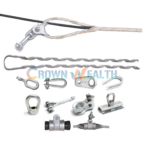
As a supplier, we also offer a range of related products that can complement the OPGW Strain Clamps and enhance the overall performance of the power system. You can check out our Tension Clamp for Overhead Line, OPGW Performed Suspension Clamp, and Preformed Double Suspension.
Conclusion
Ensuring the grounding of OPGW Strain Clamps is a critical aspect of power system safety and reliability. By selecting the right grounding materials, installing them properly, testing the grounding system, and performing regular maintenance, we can ensure that the OPGW Strain Clamps provide a reliable and low - resistance path for fault currents to flow into the ground.
If you are interested in our OPGW Strain Clamps or have any questions about grounding systems, please feel free to contact us for procurement and further discussions. We are committed to providing high - quality products and professional technical support to meet your needs.
References
- IEEE 80 - IEEE Guide for Safety in AC Substation Grounding
- IEC 61936 - 1 - Power systems with voltage levels above 1 kV a.c. - Part 1: General requirements for electrical installations